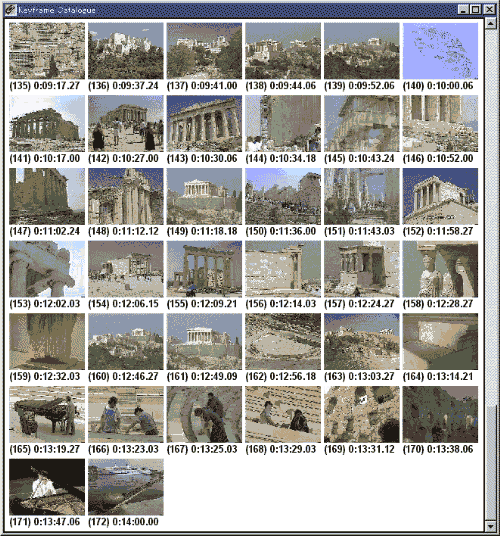
Figure 1. A video browsing interface using keyframe extraction approach. The first frame for each shot is selected as a keyframe.
Crowne Plaza Hotel, Seattle, USA
Browsing is a fundamental function in multimedia systems. This paper presents PanoramaExcerpts -- a video browsing interface that shows a catalogue of two types of video icons: panoramic and keyframe icons. A panoramic icon is synthesized from a video segment taken with camera pan or tilt, and extracted using a camera operation estimation technique. A keyframe icon is extracted to supplement the panoramic icons; a shot-change detection algorithm is used. A panoramic icon represents the entire visible contents of a scene extended with camera pan or tilt, which is difficult to summarize using a single keyframe. For the automatic generation of PanoramaExcerpts, we propose an approach to integrate the following: (a) a shot-change detection method that detects instantaneous cuts as well as dissolves, with adaptive control over the sampling rate for efficient processing; (b) a method for locating segments that contain smooth camera pans or tilts, from which the panoramic icons can be synthesized; and (c) a layout method for packing icons in a space-efficient manner. We also describe the experimental results of the above three methods and the potential applications of PanoramaExcerpts.
Camera parameter estimation, Key-frame extraction, Layout, Packing problem, Panoramic image, Scene change detection, Shot-change detection, User interface, Video analysis, Video browsing
Techniques for synthesizing panoramic images from an image sequence are attracting great attention. A panoramic image can be automatically created from multiple images by aligning and overlapping them using an image registration technique[Brown]. Panoramic image synthesis has many applications, including virtual reality[Teodosio93b], model-based video compression[Anandan], and video re-purposing[Massey] (e.g. creation of high-resolution images for publishing). Panoramic images have also been investigated as an intermediate representation for 3-D scene recovery and moving object recognition[Szeliski]. In addition, panoramic images can be used as a synoptic view of a scene[Anandan].
In this paper, we focus on the application of panoramic image synthesis to video browsing interfaces, which facilitates tasks to find a specific scene in a large collection of video data and is an important component in many multimedia systems. This application area has not been fully investigated yet, though there has been some work[Tonomura93]. The panoramic image synthesized from a scene is an efficient representation of the scene, and is useful for video browsing.
The difference between previous work and ours comes from the fact that we deal with long edited videos composed of multiple shots, while most previous papers assumed a contiguous image sequence as input. Here, a shot refers to a contiguous video sequence taken with a single camera, while a scene is defined as a semantic unit composed of shot(s). To deal with long edited videos, video analysis techniques must be efficient, and more importantly, additional processing is required for segmenting the video into individual shots, and for locating segments that contain smooth camera operations from which visually good panoramas can be synthesized. Previous work has not addressed such problems.
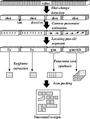
This paper presents PanoramaExcerpts, a video browsing interface that shows a catalogue of panoramic and keyframe icons. We propose a set of techniques to automate the generation of PanoramaExcerpts. The remainder of this paper is organized as follows: In section 2, we describe related previous research on video browsing interfaces and panoramic image synthesis. In section 3, the process of generating PanoramaExcerpts is outlined. In section 4, a method is proposed for detecting shot changes, such as cuts and dissolves, with adaptive control over the sampling rate. Section 5 describes a method for estimating camera parameters, and proposes a method for enumerating segments from which visually good panoramic icons can be synthesized. In section 6, a layout method is presented for packing icons in a space-efficient manner. In section 7, the effectiveness and some potential applications of PanoramaExcerpts are discussed. Section 8 concludes the paper.
It is time-consuming to scan a long video to find a specific scene and to grasp the entire contents of the video. Browsing interfaces facilitating such tasks are crucial in video applications.
One approach is to construct and display a catalogue of keyframes, as shown in Figure 1, which are representative images extracted from video sequences[Aigrain94],[Tonomura94]. This static representation of video data, which is inherently dynamic, is useful as a visual index or a storyboard for video editing. This conversion also makes it possible for videos to be printed and to be put into other forms, such as HTML documents[Shahraray].

The issue is how to extract a set of keyframes that well represent the contents of a video. One common approach is to segment the video into shots and to select one or a few keyframes from each shot. A trivial method is to select the first frame of a shot as its keyframe. For automatically selecting more representative keyframes, some researchers proposed to use motion analysis[Pentland], and color features[Zhang95].
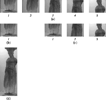
A limitation of this keyframe extraction approach is that it is not always possible to select keyframes that well represent the entire image contents. To explain this limitation, consider the sequence shown in Figure 2(a), where the camera tilts up from 1 to 5. The first frame in the sequence(Figure 2(b)) is obviously inappropriate as its keyframe, because it shows only a part (the foot of a sculpture), and it is difficult even to tell that the object in the image is a sculpture. The first, middle, and last frames 1, 3, 5 shown in Figure2(c) could be keyframes, and they better represent the shot contents. The problem is, however, that one cannot easily recognize how these frames relate each other.
The solution we propose is to synthesize the panoramic image by compositing the sequence, as shown in Figure 2(d). It represents the entire contents of the sequence in an intuitive manner.
The use of panoramic images for video browsing has been mentioned in [Aigrain96],[Teodosio93a], [Sawhney], and [Tonomura93]. Massey and Bender[Massey] applied panoramic images, what they called salient stills, to the generation of a comic book from a video. Their tools allow an artist to create a comic book by laying out salient stills as pages. However, the artist has to manually select segments for constructing salient stills, and this selection task is time-consuming. Although human intervention is inevitable and preferable for their application, it is impractical for other applications, such as video database browsing. To our knowledge, no implemented system fully automates the process of enumerating and synthesizing panoramic images from a video.
The integration of panoramic icons with video browsing interfaces causes another problem: panoramic icons have irregular shapes according to the camera operations, while keyframe icons are all rectangular and of the same size; and, this requires a sophisticated method for efficiently laying out irregular panoramic icons to create a compact catalogue view.
The process of synthesizing the panoramic image from an image sequence involves two steps: (1) camera parameter estimation, and (2) image composition.
The first step is to align two consecutive images in the sequence, that is to estimate how the camera was operated between the two images. A class of image coordinate transformation is assumed to align the two images; it can be translation, affine, quadratic, or projective transformation[Mann]. We call the transformation parameters camera parameters here. To estimate the camera parameters, various methods can be used, including the least square method, the M-estimation method[Sawhney], a method based on motion vectors[Teodosio93a], and a method based on projected gradient maps, called video X-ray[Akutsu].
The second step is to composite the images into a single panoramic image by warping the images with the estimated camera parameters. The overlapping pixels are blended with a median or mean operation, or can be just replaced by the last one[Teodosio93a]
Most of the previous work aimed to improve the quality of panoramic images, and the robustness to object motion. In contrast, we aim to construct panoramic icons, and thus quality is less important. What is important for our purpose is to reliably and efficiently process long edited videos. Note that it is not always possible to synthesize visually good panoramic icons for all shots, because camera parameter estimation is unreliable in the presence of significant object motion. To avoid this problem, we propose in section 5 a method for enumerating segments from which visually good panoramic icons can be constructed.
The following three sections detail steps 1, 3, and 5 in this order.
Segmenting a video into shots is the first step in generating a PanoramaExcerpts interface. This section proposes a new method for detecting shot changes, such as cuts and dissolves.
A simple way to detect shot changes is to count the number of pixels that change in pixel value by more than a specified amount, and to decide that a shot change is present if the total number of changed pixels exceeds a threshold. This method is called pixel-wise difference method. The problem is that it is sensitive to camera and object motions. To make shot-change detection robust to motion, a number of methods have been proposed. There are four basic approaches.
The first approach is a straightforward one that employs motion analysis. Zhang et al.[Zhang93] used optical flow analysis to discriminate motion from dissolves. Zabih et al.[Zabih95] compensated global motion before computing the edge change fraction. However, this approach tends to be computationally expensive.
The second approach is to use some difference measures insensitive to motion, such as intensity histogram difference[Tonomura90] and color histogram difference[Nagasaka]. This approach is quite efficient, but it sometimes misses changes between shots whose background is similar in intensity or color.
The third approach is to exploit a spatial property;
a cut induces a significant change spreading almost all over the frame,
while motion yields a local change.
Nagasaka and Tanaka[Nagasaka] divide a
frame into 16
blocks, and compute a
![]() difference measure for each block;
the total of the 8 smallest measures are thresholded to detect a
cut. Hampapur et al. also used a similar idea[Hampapur].
difference measure for each block;
the total of the 8 smallest measures are thresholded to detect a
cut. Hampapur et al. also used a similar idea[Hampapur].
The last approach is to rely on the assumption that camera and object motion is smooth over time. Otsuji and Tonomura[Otsuji] proposed a temporal filter to eliminate motion-induced change based on this assumption. One problem is that their filter also eliminates change induced by gradual transitions.
Figure 4 shows the process flow of our proposed method. The method: (1) successively samples a sequence of M frames from a video at a sampling rate, (2) labels the sequence for each pixel based on the temporal variation, and (3) decides if a shot change is present in the sequence or not; (4) after the labeling step, the sampling rate is checked and adjusted if not appropriate. We describe steps (2) and (4) in the following sections.
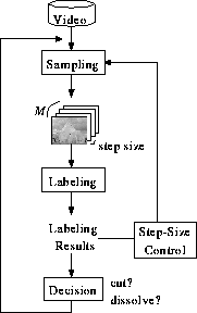
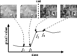
To distinguish motion from shot changes, we use the observation that the variation induced by shot changes is ``systematic'' or ``artificial'', while that induced by motion is rather ``random''. A cut induces ``systematic'' variation in that pixel values tend to instantaneously change at a cut point, as illustrated in Figure 5. Similarly, during a dissolve, pixel values tend to linearly increase/decrease. In contrast, in the presence of motion, pixel values tend to vary randomly.
Based on this observation, we classify the temporal variation of each
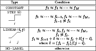
pixel into four types: CONSTANT, STEP,
LINEAR, and NO-LABEL, as listed in Table 1.
We use simple thresholding for the classification in our current
implementation.
Label CONSTANT is defined by
![]()
where ![]() is the pixel value at a pixel point in
the i-th frame, and
is the pixel value at a pixel point in
the i-th frame, and ![]() means that pixel value a nearly
equals b; specifically, when the difference between
means that pixel value a nearly
equals b; specifically, when the difference between ![]() , i.e.,
, i.e.,
![]() , is less than a threshold, the pixel point is
marked as CONSTANT.
Similarly, STEP and LINEAR labels are assigned to the
pixel point if it satisfies the conditions listed in Table
1 (STEP and LINEAR labels have parameters, i
and j, to specify the characteristic positions). Otherwise, the
pixel point is
marked as NO-LABEL. For example, at the pixel point depicted
in Figure
5, STEP(3) is
assigned. This labeling procedure is
repeated for all pixel points.
, is less than a threshold, the pixel point is
marked as CONSTANT.
Similarly, STEP and LINEAR labels are assigned to the
pixel point if it satisfies the conditions listed in Table
1 (STEP and LINEAR labels have parameters, i
and j, to specify the characteristic positions). Otherwise, the
pixel point is
marked as NO-LABEL. For example, at the pixel point depicted
in Figure
5, STEP(3) is
assigned. This labeling procedure is
repeated for all pixel points.
The number of assigned labels for each type indicates what kind of
change is present in the sequence. For example, the number of
STEP(i) labels increases when a cut is present at the
i-th frame in
the sequence. Our method declares that a cut is present at the
center of the sequence if
![]()
where N is the number of pixels in a frame, #STEP
denotes the number of STEP labels, and the left-hand side is
called the cut measure.
Similarly, it declares that a dissolve is present if ![]()
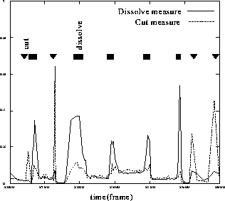
Figure 6 shows an example of the cut
and dissolve measures.
This labeling method can be seen as an extension of the pixel-wise difference method described above. Our method classifies the temporal variation in pixel value based on M frames into four types; on the other hand, the pixel-wise difference method classifies the variation based on two frames into two: changed or not.
The above procedure takes as input M frames sampled from a video at a certain intervals. We call this sampling interval the step size. The larger the step size, the more efficient the processing. However, when the step size is too large, detection performance is degraded due to rapid motion.
We propose a step-size control mechanism for efficient processing while maintaining the detection performance. The step-size is adaptively controlled based on the labeling results so that the step size is set to small in the presence of motion. The number of NO-LABEL indicates the degree of motion, and if #NO-LABEL is larger than a threshold, the step size is halved. On the other hand, if #CONSTANT is larger than a threshold, the step size is doubled. The most time-consuming step in detecting shot changes is in general to read images from external devices such as hard discs and remote file servers; the adaptive step-size control mechanism reduces the number of images to be read and results in faster processing.
We tested our method on various videos, including news
programs, sports programs, and travelogues.
To evaluate its performance, we use the recall and precision
measures[Boreczky] defined by
![[equation]](img17-6.gif)
where ![]() ,
,
![]() ,
and
,
and ![]() are the numbers of correctly detected shot changes, missed ones,
and false positives, respectively.
are the numbers of correctly detected shot changes, missed ones,
and false positives, respectively.
The experimental results are tabulated in Table 2. Though it is difficult to compare the performance of the previous methods to ours because they were evaluated on different videos, the recall and precision measures are comparable to or better than the reported ones in [Boreczky]. Our method gave false alarms in the presence of significant motion, for example, in a scene in which a car quickly passed through the frame. Shot changes before and after a significant motion are sometimes missed, because #NO-LABEL increases in such a scene. The ``Soccer'' video gave the worst results in the tested videos. The video contains rapid camera operation and quick object motion. To make matters worse, most shots had a large common background in the green field.

The step-size control mechanism made it possible to efficiently process video data while maintaining good performance. In the ``Greece'' video, the average step size was 5.9, i.e., the average sampling rate was 5.2 frames per second. When we processed the entire video with the fixed step size of 6, the number of missed detections increased by 11, while the number of false alarms did not change.
Note that the step-size control mechanism helps not only to accelerate processing but also to improve the performance of dissolve detection. The slower the dissolve, the more difficult it is to detect it, because the difference between closely sampled frames (e.g. 1/30 second interval) in a slow dissolve is too slight to be stably detected. The step-size control mechanism allows our method to use as large step size as possible, and this helps to reliably detect slow dissolves.
With a large step size, quick dissolves were sometimes classified into cuts. To prevent this error, the method can be modified to closely examine detected segments with a smaller step size.
To compare our method with previous ones, we tested our method on three of the image sequences, ``Clapton'', ``Energizer'', and ``Spacewalk'', used by Zabih et al. [Zabih95b]. This experiment found that our method tends to miss shot changes in the presence of motion, instead of giving false alarms. In the ``Energizer'' sequence, one shot change was missed because there was a significant object motion just before the shot change; Zabih et al. reported that their method also gave a false alarm at this point. The ``Spacewalk'' sequence contains camera-gain effects, which are caused by the change of the camera gain and result in instantaneous changes in overall area of images. While Zabih's method gave false alarms due to the camera-gain effects, our method successfully avoided the false alarms. This is because our method classifies the camera-gain effects as NO-LABEL as different from STEP and LINEAR. The ``Clapton'' sequence contains two dissolves which Zabih's method successfully detected. Our method missed both of them. Perhaps, this is partly because the outgoing shot contains object motion.
To construct visually good panoramic icons, we need to locate segments with stable camera operations. This process is divided into three: (1) estimating camera parameters, (2) validating the estimated parameters, that is checking if the estimated camera parameters are reliable, and (3) classifying the parameters into pan, tilt, or a mixture of these. This section describes a method for estimating camera parameters, and proposes a criterion to validate the estimated parameters.
The issue is to estimate the image coordinate transformation that
aligns two consecutive frames f and
f'. For computational efficiency, we use the simple translation
model defined by
![]()
where (x,y) is a point in f, (x',y') is the corresponding
point in f', and
![]() is the camera parameter that needs to be estimated. This approximately models camera
pans and tilts when
the focal length is large. For estimating the camera parameters,
we use the least square method, that is to say, mean
square error
is the camera parameter that needs to be estimated. This approximately models camera
pans and tilts when
the focal length is large. For estimating the camera parameters,
we use the least square method, that is to say, mean
square error ![]() defined by
defined by
![]()
is minimized, where N denotes the number of corresponding pixels, and
the summation is calculated over all the corresponding pixels between
f and f'. The coarse-to-fine strategy[Anandan] is used to
minimize ![]() .
.
This section proposes a criterion for validating the estimated parameters. When all the following conditions are satisfied, the camera parameters in a segment I=[s, e] are judged to be valid.
The valid segments should contain only stable camera pans and tilts, because we use the translation model; once valid segments are extracted, it is easy to classify the camera operations into pan, tilt, and a mixture of these.
The third condition is important to distinguish camera motion from
object motion. You might think that it is possible to modify this
condition like ![]() , but this is not
successful. We found that
, but this is not
successful. We found that
![]() increases with the amount of texture in a
scene. This makes it difficult to set a fixed threshold. From a
theoretical point of view, this condition is equivalent to
the likelihood ratio test, provided that residual f(x,y)-f'(x',y') is
assumed to be normally distributed with mean zero.
increases with the amount of texture in a
scene. This makes it difficult to set a fixed threshold. From a
theoretical point of view, this condition is equivalent to
the likelihood ratio test, provided that residual f(x,y)-f'(x',y') is
assumed to be normally distributed with mean zero.
The validation procedure itself is not computationally expensive,
since ![]() and
and ![]() are
already computed in the camera estimation process.
are
already computed in the camera estimation process.
We tested the above methods on three videos. We compared the pan-tilt segments detected by our method with manually extracted ones. When a detected segment contained a camera zoom, it was scored as a false positive. The experimental results are summarized in Table 3. The results demonstrate that 71% to 94% of pan-tilt segments were successfully detected. The main cause of missed detection was significant object motion in the segments. This is preferable for us because the panoramic icons synthesized from such segments are not visually useful. The false positives were caused by scenes containing significant object motion on a defocused background.
The above third condition, goodness-of-fit, was found important for preventing false positives. When we omitted the condition, 8 additional false positives arose in the ``Greece'' sequence.

In this section, we propose a method for packing icons within a two dimensional region (e.g. in a window) in a space-efficient manner. Panoramic icons have different shapes and sizes depending on the camera operations, and this makes it difficult to lay icons out. It is possible to use a variety of layouts for packing icons; for example, icons can be resized or removed if not important. Here, we do not deal with layouts that allow resize and removal.
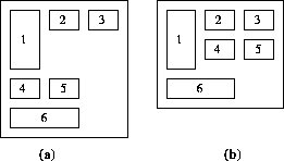
A naive layout method that places icons left to right into multiple lines produces large dead spaces as shown in Figure 7(a). This means that the amount of information packed in a page or a window becomes less. A method is required for efficiently packing icons within a two dimensional region. Intuitively speaking, our proposed method allows a line to be subdivided into multiple rows, as illustrated in Figure 7(b), for efficient space utilization.
The packing problem in general is a well studied problem in the operational research field[Dowsland]. A typical problem is, given a set of rectangular pieces and a container of given width and undetermined height, to minimize the height required to fit all the pieces. The problem is known to be NP complete, and a number of heuristic methods have been developed.
These methods were primarily developed for non-interactive applications, such as VLSI design, and are not suited for our purpose, because the following requirements have to be met:
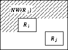
Let us consider rectangular pieces ![]() , each of which
corresponds to the bounding box of an icon.
To preserve the ordering of
, each of which
corresponds to the bounding box of an icon.
To preserve the ordering of ![]() , we impose the following constraint
, we impose the following constraint
![]()
where ![]() denotes the area northwest to piece
denotes the area northwest to piece
![]() as
depicted in Figure 8. Constraint
(1) prohibits the subsequent pieces
as
depicted in Figure 8. Constraint
(1) prohibits the subsequent pieces
![]() from
overlapping region
from
overlapping region
![]() .
.
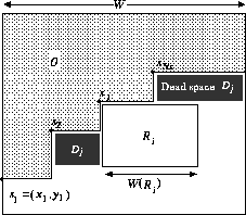
The proposed heuristic method successively places each piece in such a way that the dead space produced by the placement is minimized under the above constraint. Our proposed heuristic method is as follows:
To compare our method with the naive method, we define packing ratio
PR as
![]()
where
![]() and
and
![]() denote the height of the layout
generated by our proposed method and the naive
one, respectively. Packing ratios under 1 indicate that
our method is better than the naive one.
Note that our method is not assured of yielding the optimal results; our method
may provide worse layout than the naive method.
denote the height of the layout
generated by our proposed method and the naive
one, respectively. Packing ratios under 1 indicate that
our method is better than the naive one.
Note that our method is not assured of yielding the optimal results; our method
may provide worse layout than the naive method.
First, we tested our method on randomly generated datasets. We generated 100 datasets of 500 pieces, whose width and height were randomly selected from 0 to 100; The packing ratio was measured for each dataset by varying container width from 100 to 1200. The experimental results are shown in Figure 10(a). Our method gave better results than the naive methods for all the datasets regardless of the width of container.
Next, we tested our method on a real dataset, containing 143 keyframe icons, 80 by 60 pixels in size, and 30 panoramic icons of different extent. The packing ratio was measured by varying container window width. The results are shown in Figure 10(b). As the window width increased, the packing ratio decreased to about 0.85. This means that about 15% of the screen space was saved.
The computational cost for packing was small compared to that needed to
redraw images. The time complexity is ![]() .
.
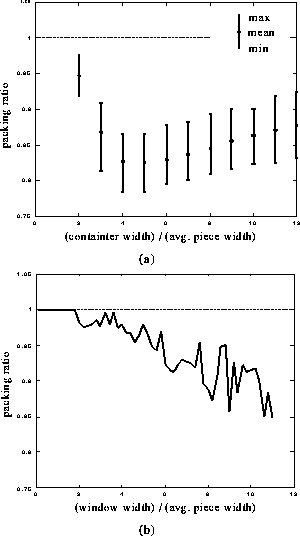
Figure 11 shows an example of PanoramaExcerpts generated from a travelogue on Greece. First, the panoramic icons efficiently represent the shot contents by providing coherent images, e.g. the buildings (144), (146) and the sculpture (159). Compare them to the corresponding keyframe images shown in Figure 1. Second, the contour of a panoramic icon indicates the camera operation in the corresponding shot; for example, a shot with camera pan is represented by a wide panoramic icon , e.g. (135) and (153). Finally, the succession of the representative images shows the global structure of the video, what kinds of scenes appear in the video in what order.
The effectiveness of the PanoramaExcerpts interface depends on the category of target videos. We generated PanoramaExcerpts from a variety of videos. For categories of video that contain a lot of camera operations, such as travelogues, PanoramaExcerpts seems to make sense. On the other hand, for videos with few camera operations, such as news programs, PanoramaExcerpts is almost equivalent to the conventional catalogue of only keyframe icons.
The temporal order of icons was easily recognized in most cases. However, when there were a lot of camera pans and tilts in the sequence, some difficulty might occur. We could resize or eliminate some of keyframe icons for a more efficient and readable layout.
Functions assigned to icons in our prototype system include playing the corresponding video segment on a monitor window, deleting a redundant icon, inserting ``carriage return'' after an icon, and copying an icon image to the system clipboard. These functions allow users to edit the automatically generated PanoramaExcerpts interface to match their needs.
The time needed for generating the PanoramaExcerpts was about the same as the duration of the input video, when images of 160 by 120 in pixel are processed at the rate of about 10 frames per second. The most time-consuming step was estimating the camera parameters.
We discuss some potential applications of PanoramaExcerpts below.
A straightforward application of PanoramaExcerpts is to video browsing interfaces for video database systems, such as VOD systems; it can be used for browsing video retrieval results, for logging stocked videos in printed and electric forms, and for browsing video footages in editing videos.
As described in the introduction, techniques for panoramic image synthesis can be applied for video re-purposing, such as for publication or web content production. Software for creating high-resolution panoramas from a video will benefit from the PanoramaExcerpts. Video tapes usually contain a lot of scenes, and this makes it time-consuming to find a segment for creating a panoramic image. With the PanoramaExcerpts, the only thing the user has to do is to select an icon in the catalogue.
The information derived during the generation process, such as shot-change positions, camera operation types, and resultant panoramic images are useful as indices for video databases. The information can then be used for retrieval and browsing.
![[img]](panoex.gif)
This paper presented PanoramaExcerpts, an advanced technique that combines panoramic and keyframe icons to facilitate the browsing of videos. For automatically generating PanoramaExcerpts, we have developed a shot-change detection method, a method for camera operation estimation and validation, and an icon layout method.
Further research topics include: subjective evaluation of PanoramaExcerpts interfaces, extension to the shot-change detection algorithm to cope with wipes and other transition effects, refinement of the camera parameter estimation method to deal with camera zoom operations, and developing techniques for more efficient processing.
The authors would like to thank Dr. Yukio Tokunaga for his support of our research. Thanks are due to Dr. Hiroshi Hamada for valuable discussions on research directions. We would like to thank Dr. Takashi Satoh for reading the draft and making a number of helpful suggestions. We also wish to thank our colleagues for their constant help and discussions. All video images were reproduced by NTT Human Interface Laboratories with the permission of the copyright holder Bungeishunju Ltd.